As soon as I got this car, I decided to install an electronic ignition device from the “123Ignition” company in Holland. The engine already started very well with its original ignition device but an electronic one gives more reliability and regularity.
2cv_101
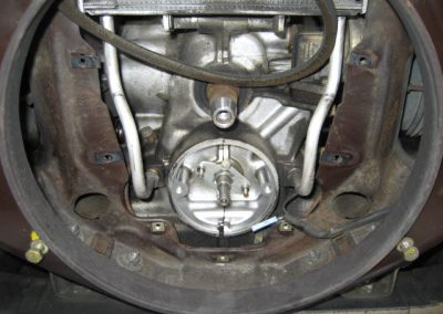
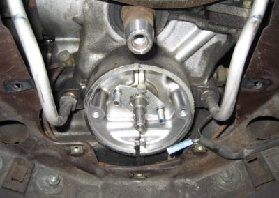
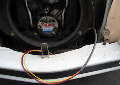
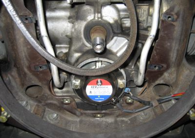
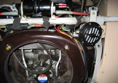
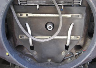
Here is how it looks like when the cooling fan, protecting rubber and original ignition device have been removed
2cv_104
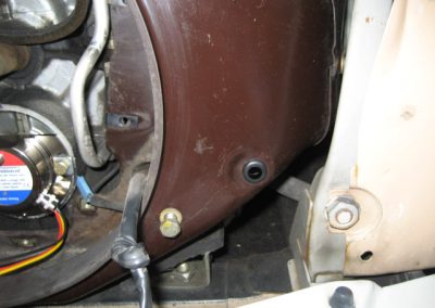
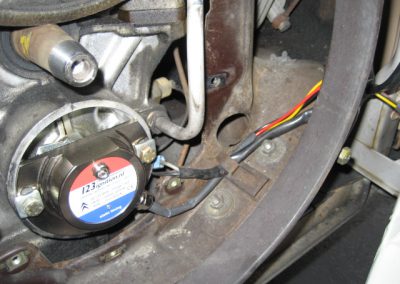
A new wiring pass-thru is included in the kit, it’s bigger than the original one, because of the additional wires
2cv_108
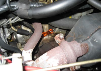
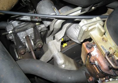
To adjust the device, the ignition setting point must be found. To do that, I insert a 6 mm shaft (a drilling bit does a great job) in the hole shown here with a screwdriver
2cv_109
Then I turn the engine flying wheel until the shaft finds its corresponding hole on the flying wheel. I am now exactly on the ignition setting point (8 degrees before Top Dead Center). I mark it with a little bit of paint
2cv_110
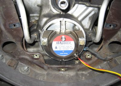
I do some connections and I begin to adjust. First, it’s a rough setting, engine not running, with a LED on the device box. I turn the box until the LED comes on at the ignition point previously set
2cv_111
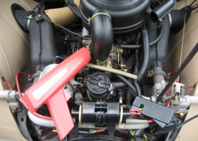
Then I do a finer adjustment with a stroboscopic lamp, this time with the engine running (and the 6mm shaft removed, of course). I use the paint mark to fine tune the ignition point
